🗺️3.3 Get3D Mapper
This section will introduce you to how the functions of the software interface are used
Last updated
This section will introduce you to how the functions of the software interface are used
Last updated
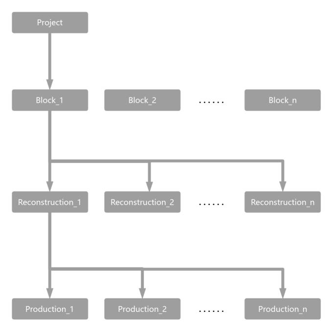
Get3D Mapper is the main user interface, the software project is a tree-like structure, which contains multiple blocks under the project; different reconstruction frameworks can be created under the blocks according to the requirements; and multiple different types of product results can be submitted under the reconstruction frameworks.
After opening Get3D Mapper software, click New Project or Project >New Project or use the shortcut key "Ctrl+N". Open the New Project page. On the New Project page, you can set the project name and project directory. If cluster computing is required, set the project path to the network path.
Click Project > Open Project, select the *.m3d project file, and click Open. You can also open the project by clicking "Project Name.m3d" in the Recent Projects list.
Click Project > Save Project button or use the shortcut key "Ctrl+S" to save the project information.
Project processing is complete, click the Project > Clean Project function to clean up the completed project. If the project has a task running, you can not perform this operation. It does not contain the product results generated by the software.
① Clean Project Cache
Project cache includes AT feature point files(KeyPoints folder) and thumbnail file(Preview folder).
② Clean Block Cache
Block cache includes AT match files, bundle files and other setting files(Block/Cache folder).
③ Clean Reconstruction Cache
Reconstruction cache includes dense matching point files(Block/Reconstruction/cache_points folder).
④ Reconstruction Tile Cache
Reconstruction tile cache includes tile’s midout results(Block/Reconstruction/Tile folder)
⑤ Clean Reconstruction Log
Reconstruction log includes production log files(Block/Reconstruction/Productions/Production/Tile folder).
Quickly clean up files by selecting the corresponding cache.
Click Project > Close Project, and select Yes in the pop-up box to close the project.
Click Project > Exit or use the shortcut key "Ctrl+W" to close Get3D Mapper.
Add Images
Get3D Mapper supports importing aerial photos and ground photos, you can organize your data according to the file specification, and choose to import as needed according to the actual scene.
After importing the data, the images need to be further positioned to restore their pose. Get3D Mapper supports positioning methods such as EXIF (Exchangeable Image File Format) data and pose files.
EXIF Positioning
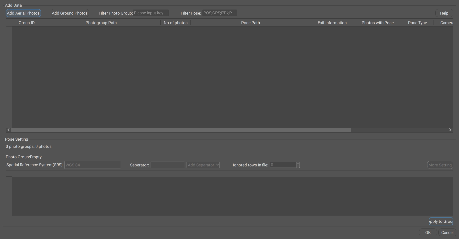
1) Add photos
Select the root directory of the file to import all the photos under the folder.
2) Read Exif location
Check the Exif information column, select the "exist" photo group, right click to open the menu bar, click Read Exif button.
3) Query
4) Progress bar
5) Positioning completion
After the positioning is completed, "0/2250" is switched to "2250/2250", i.e. each photo in the photo group has positioning information corresponding to it.
Pose File Positioning
1) Add photos
2) Automatic matching of photo groups and pose files
a) Automatic Matching
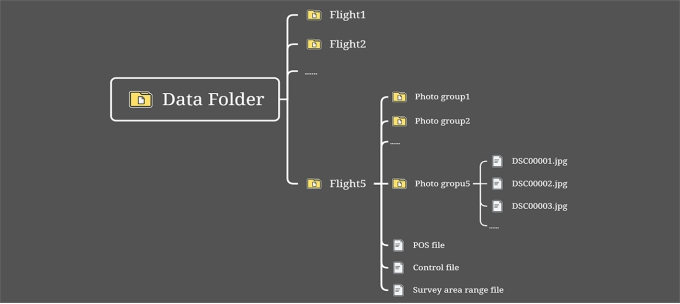
Pose files are stored in the way shown in the following figure, Pose file name contains keywords such as POS; GPS; RTK; PPK, etc. After importing photos, the photo group will automatically correspond to the pose file.
Tip: Pose file does not contain (POS; GPS; RTK; PPK) keywords, you can set the keywords manually, select the photo group, right-click and use the menu bar, automatically search by keywords.
b) Manual Correspondence
3) Selection of the Pose file
Batch select multiple groups of photos by right-clicking to open Select Pose File in the menu bar.
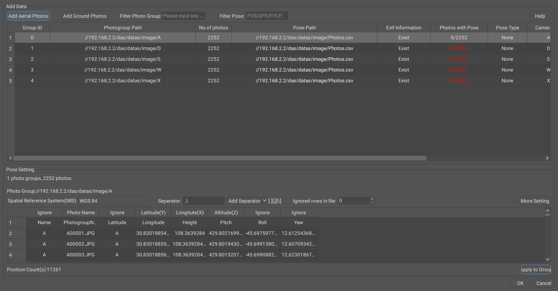
4) Define the pose format template
Set the spatial reference of the Pose, the separator, and the actual meaning of each column ("photo name, longitude, latitude, elevation" or "photo name, east coordinate, north coordinate, elevation").
5) Apply to photo groups
After defining the template, click Apply to Group to select the photo group.
6) Positioning completion
After the positioning is completed, "0/2250" is switched to "2250/2250", i.e., each photo in the photo group has positioning information corresponding to it.
Add Video
Get3D Mapper supports adding videos to get the corresponding video frames and add them to the block image. In the Data Manage interface, click the Add Video button, set the input and output file paths, and set the start and end of the extracted video frames as well as the interval time, then you can extract the imported video frames directly.
Add Mobile Scan
Get3D Mapper supports the addition of laser point cloud and track line data collected by mobile laser equipment. The software supports laser point cloud modeling alone and laser point cloud fusion modeling with photos.
Support vehicle-mounted, airborne, backpack, and handheld laser point clouds. Laser point cloud supported formats: *.las, *.ptx, *.pts, *.e57. Trajectory line supported formats: *.txt, *csv.
1) Open the Add Mobile Point Cloud interface
2) Setting up the laser point cloud spatial reference
3) Selection of mobile laser point cloud data
4) Importing trajectory lines
5) Define the trajectory line
Set the spatial reference of the track line, the separator, and the actual meaning corresponding to each column ("GPS time, longitude, latitude, elevation" or "GPS time, east coordinate, north coordinate, elevation").
6) Enquiry
Whether you need to check for data matching.
7) Check the matching results
Laser point cloud check contains laser point position and track line position matching; laser point cloud time and track line time matching. And display the matching status.
8) Data Manage interface display
Add Static Scan
Get3D Mapper supports adding laser point cloud and center data collected by a stationary laser equipment. The software can support laser point cloud modeling alone and laser point cloud and photo fusion modeling. The following formats are supported: *.las, *.ptx, *.pts, and *.e57. The station center supports manual input or import of *.txt format files.
1) Click Add Static Scan
2) Select the point cloud coordinate system
3) Add Point Cloud
4) Add Station Center:
There are two ways to add station center coordinates:
One is to manually add station center coordinates on the right side of the point cloud list.
The other is to click Add Station Center, import the center of the station coordinates file. File samples such as the figure below, including the point cloud name, x, y, z arrangement, separated by a space in the middle:
If there is no station center coordinates, the software can automatically calculate, uncheck the Define station center.
Add Control Points
Add control points to the Data Manage view, as a block split reference, or as an imported photo data integrity reference.
1) Open Add Control Point
2) Selection of control point file
3) Define the control point file format
Set the spatial reference and delimiter. Define the control point file as "point name, longitude, latitude, elevation" or "point name, east coordinate, north coordinate, elevation".
The following is an introduction to the interface functions:
4) Successfully importing control points
5) Clear control points
The added control points can be clear by click Clear Control Points.
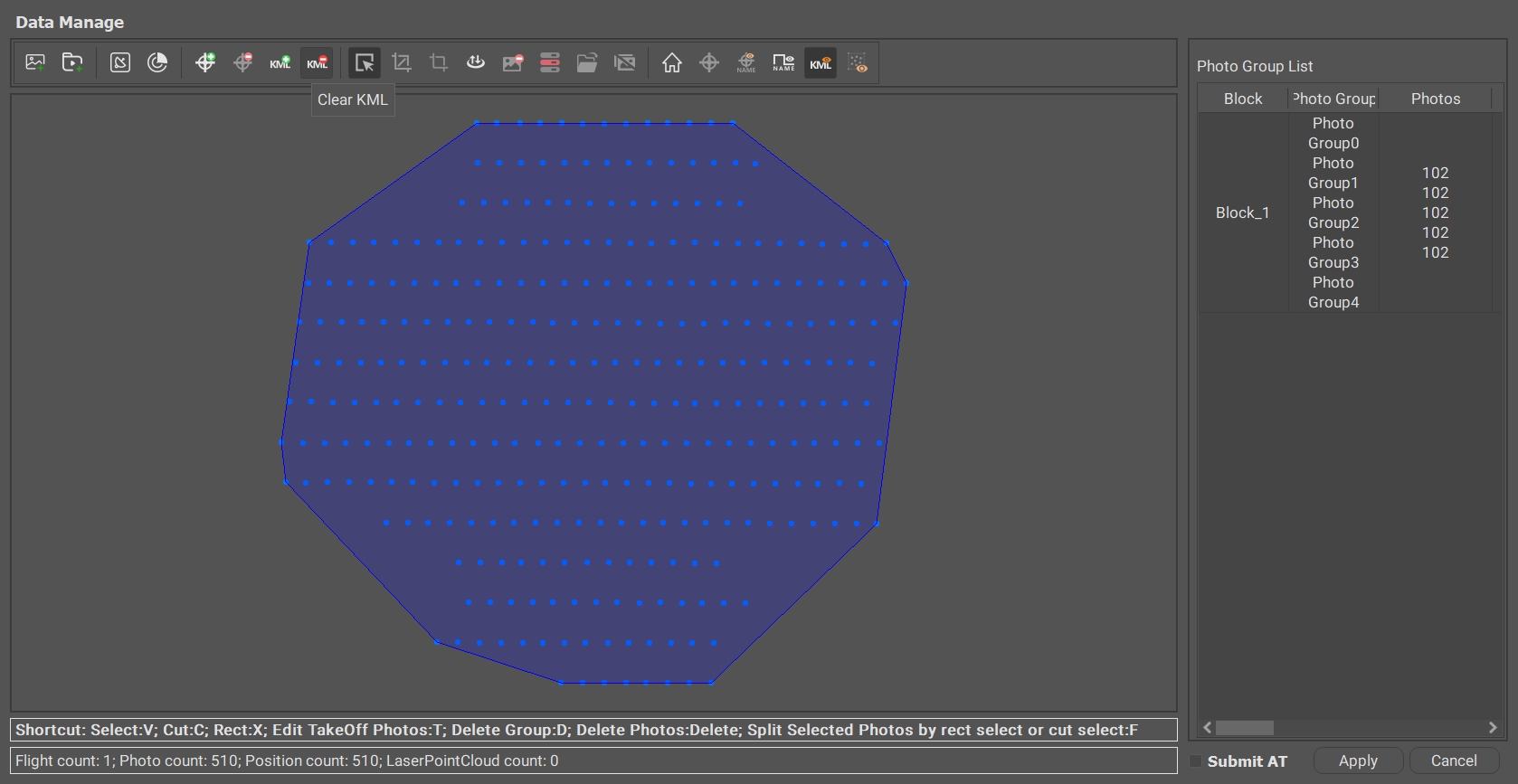
Add KML
KML, which stands for Keyhole Markup Language and was originally developed by Keyhole Corporation, is a coding specification based on XML syntax and formatting for describing and preserving geographic information such as points, lines, images, polygons, and models.
a. Add the KML file
Add a range line to the Data Manage view as a reference to the data integrity of the imported photos.
Range line reference data can be imported after tilt or other multi-source data is imported in the data management interface.
b. Select the background KML file
c. Delete KML line
The imported range line data can be cleared by clicking Clear KML.
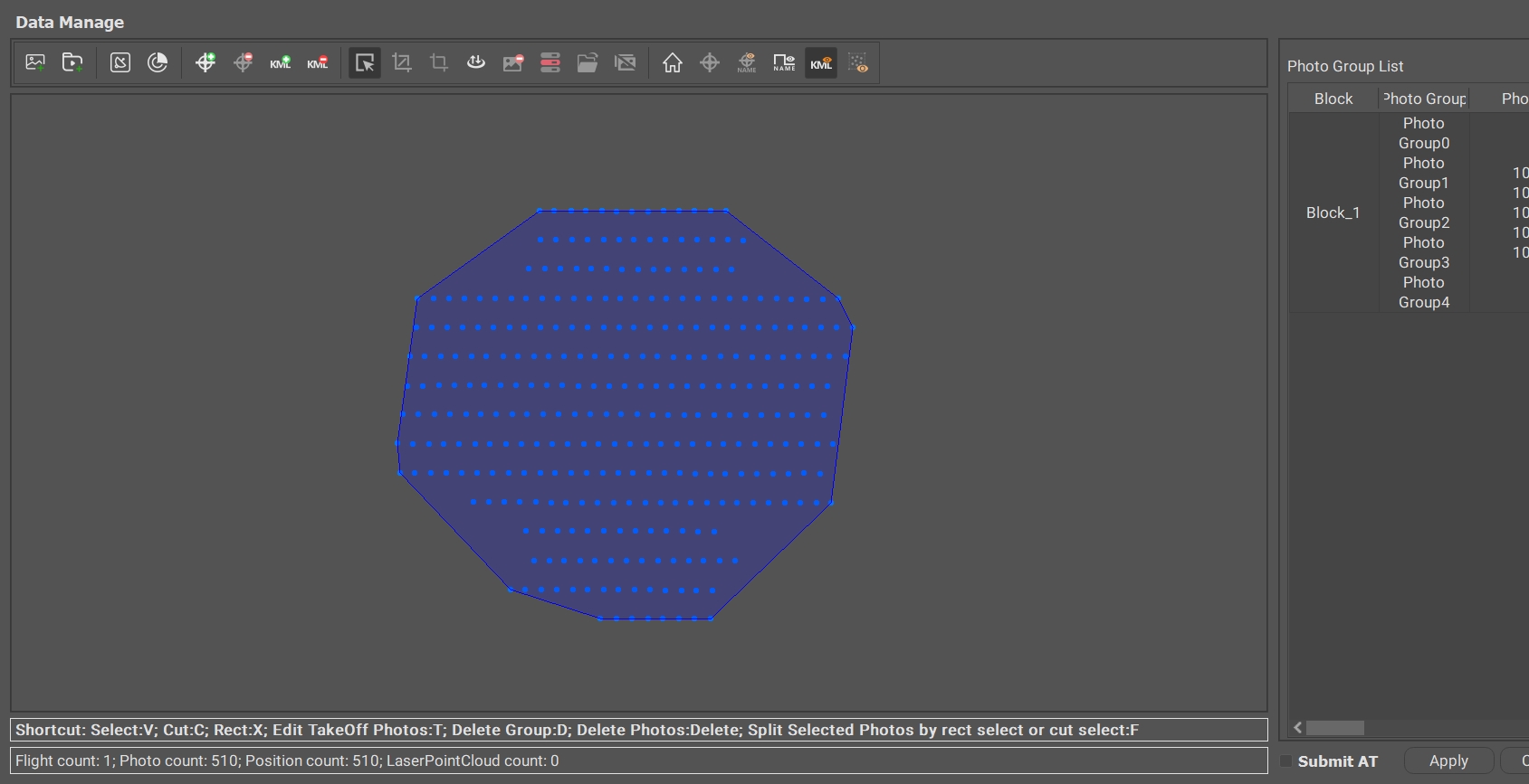
After adding photos and pose data, in the Data Manage view each photo is expanded according to the corresponding position (x y z), and editing operations such as selecting, truncating, framing, and deleting can be performed.
The photo visualization interface in the Data Manage, in the photo group list view, you can rename, block and other operations on the positioned photo group data.
Perform a save operation for the edited Aerial Triangulation (AT). For example, save the AT results after deleting photos, tie points, or control points.
Aerial Triangulation results can be exported to do Aerial Triangulation results backup or re-imported into other projects to use. Get3D Mapper supports the import of Aerial Triangulation formats: *.xml, *.xbin.
Get3D Mapper supports the export of internally generated data such as tie points, marking points information, etc. in the format of *.xml, *.xbin, *patb.
Export the POS point locations for the specified block in JPG or PDF format.
If the original photo paths have changed, to ensure that the Aerial Triangulation and Reconstruction tasks read these photos properly, you need to update the paths of the photos in the block.
Click Block > Modify Photo Directory
Click Refresh at the bottom of the screen to check before making changes.
Red: The path of the photos recorded in the block is abnormal, and there is no corresponding photo under the path.
Green: The corresponding photos can be found in all the photo paths recorded in the block.
Double click to select the new path. The photo storage structure has not changed, and other paths can be replaced automatically.
For damaged or missing images, you can delete them by clicking Delete Lost Photos.
Aerial Triangulation consists of two parts, the Relative Orientation and the Absolute Orientation.
Relative Orientation: Relative Orientation, refers to the work of restoring or determining the relative relationship of the image pairs at the time of photography, i.e. solving the work of the relative orientation elements of the stereo image pairs. It is through the observation of the image of the object in different viewpoints of the position of the relationship to determine the internal and external parameters of the camera, the relative orientation of the stereo image pairs is to restore the photography of the two neighbouring image beams of the interrelationship between the two, so that the same name of the light pairs to the intersection of the light pairs.
Absolute Orientation: Absolute Orientation is through the measurement of the ground control points, the image and the ground coordinate system for contact. It uses the known ground control points to translate, rotate and scale the relatively orientated three-dimensional geometrical model to incorporate it into the ground photogrammetric coordinate system, and to improve the absolute accuracy of AT through the control points.
After the photos are imported into the software, the first step is relative orientation to recover the internal and external parameters of each photo. The second step is absolute orientation to improve the absolute accuracy of the Aerial Triangulation.
Aerial Triangulation parameters setting:
The preset options, which contain more settings, are shown below:
For a detailed description of the AT Setting, please see the Aerial Triangulation Setting Instruction document.
Aerial Triangulation 3D View
The content displayed in the Aerial Triangulation 3D view includes information such as photo pose, tie points, control points, laser point cloud, and laser trajectory lines.
AT Report
The AT report mainly includes the following parts: project overview, camera calibration, camera information, tie point information, and control points.
Project overview: It contains the project where Aerial Triangulation is located, the running time, the number of photos, the number of control points, the number of photos entering the network, the photo ratio in net, the number of tie points, the average resolution of tie points, and the re-projection error of tie points.
Camera calibration: A detailed list of information on the internal and external parameters and distortion coefficients of the camera set, which are used to assess the calibration accuracy of the camera.
Camera information: Schematic of the offset distance of the camera position from the original POS data, schematic of the re-projection error for each photo, the number of connection points observed by the camera, and the scene coverage. Corresponding connection points, re-projection error for each photo.
Tie point information: Observation count of tie points, re-projection error of tie points.
Control points: coordinates and error information of each control point.
If the product generated only by inputting the photo positioning data does not meet the absolute accuracy requirement, it is necessary to add control points at the end of the relative orientation to get the absolute orientation result and improve the absolute accuracy of the product.
Click Edit GCP to open the control point editing interface, as shown in the figure below:
The interface is divided into four parts: Control Point Information, Marking Point Information, View Panel and Photos Preview Panel
The control point information bar displays the point information of the imported control point, and the marking point information bar displays the marking point information of each control point. The table header information is shown in the table, as shown below.
The view panel includes the Block View, 3D View, and Control Points Record.
Block View displays a 2D view of the photos and control points within the block. It is primarily used for selecting, locking, and unlocking control points.
3D View displays the spatial positions of control points, point clouds, and photos.
Control Points Record shows the point records collected in the field, which are used to determine the actual location corresponding to the marked points. Users can refer to the point record to perform marking operations.
Photos preview panel shows photos to be marked and marking tools.
Import Control Points
Click Import, select the spatial reference corresponding to the control point file, select the separator, set the name, X, Y, Z, and click OK to import the control points.
Mark GCPs
Get3D Mapper supports manual marking points and intelligent marking points.
Manual Marking:
1) Select Control Points:
In the Control Point Information Panel or Block View, select the control point to mark.
Photos containing the selected control point will appear in the Photo Preview Panel. By default, photos with the point centered are displayed first, filling the panel in a tiled layout.
2) Adjust Photo Display:
The number of photos displayed per page can be adjusted (up to 9). For example, if 4 photos are set per page, they will be displayed in an appropriate size.
3) Mark Control Points:
Photo names are highlighted with a yellow border. Selected photos are marked with a blue border.
Hold the Shift key and left-click to mark the point. The marking position is confirmed based on field data collection.
After marking, the photo name changes to a green border, and marking details appear in the Marking Information Panel.
Once two photos are marked, a red prediction box will appear in subsequent photos, guiding the marking process. For optimal accuracy, it is recommended to mark approximately 30 photos per control point. Press D to switch to the next page.
Intelligent Marking:
1) Initial Marking:
Mark two photos manually for the control point.
2) Intelligent Recognition:
Click Intelligent Recognition, and the software predicts the corresponding positions in other photos.
Photos with successful predictions are marked with a green border. Those without predictions remain with a yellow border and require manual marking.
3) Check and Confirm:
Verify the results on the current page. Adjust positions as needed.
Click Confirm Position to save the markings to the Marking Information Panel.
After confirming positions, the predicted points will change to red.
4) Repeat for Remaining Photos:
Navigate to the next page and repeat the steps until the required number of photos is marked with satisfactory precision.
Some of the common shortcuts for Mark GCPs is shown:
Save Marking Results
After completing the marking, close the marking panel and save the edits to the block file.
Create a New 3D Reconstruction or New 2D Reconstruction spatial frame on Aerial Triangulation (set up spatial references, area of interest ranges, tile divisions, reconstruction memory estimates, and more settings) under which one or more products can be submitted.
The 2D reconstruction setting is same with 3D reconstruction.
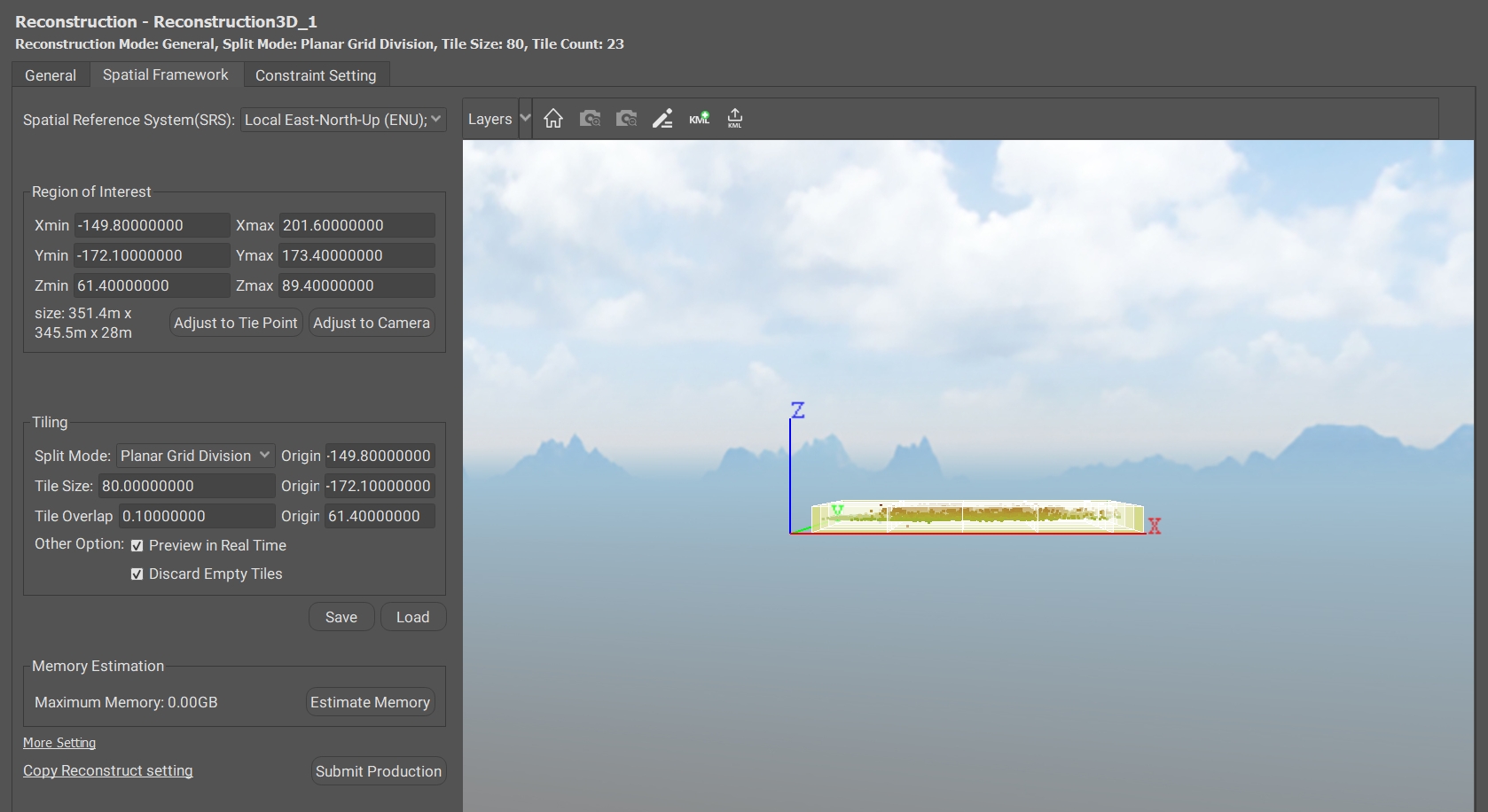
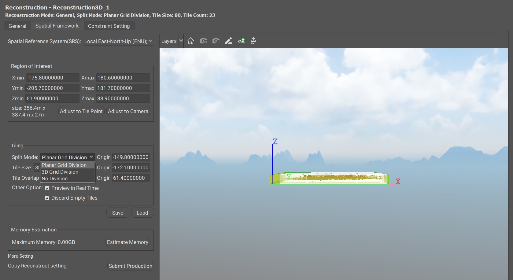
(1) Spatial Reference System
The spatial reference system is set to the ENU coordinate system (Local East-North-Up system) by default. Users can change it to an existing or custom-defined coordinate system. Using a consistent spatial reference ensures seamless alignment of tile boundaries in subsequent reconstruction processes.
Note: The reconstruction coordinate system supports only projected coordinate systems, not geodetic coordinate systems.
(2) Region of Interest
There are multiple ways to set the region of interest: quickly setting the range, editing the region in the view, or importing KML boundary lines.
Quickly set the range:
Adjust to Tie Points: The area of interest ranges to the largest outer enclosing box that contains all tie points.
Adjust to Camera: The area of interest ranges to the largest outer enclosing box containing all cameras.
Edit the region in the view:
Select Edit Region, then drag the faces of the bounding box to define the area.
Importing KML boundary lines:
Select Import KML, and import the the pre-drawn KML boundary line.
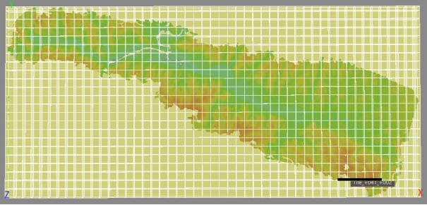
(3) Tiling
Split Mode: Planar grid division, 3D grid division, no division.
Tile Size: Set the tile length. There is a proper tile edge length by default (related to AT resolution, related to GSD), user can customize the tile size.
Tile Overlap: Set the overlap length of neighbouring tiles. When using tile reconstruction, in order to avoid gaps between tiles, set the width of overlap between tiles.
Origin XYZ: Set the coordinates of the origin of the tiles.
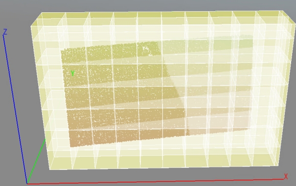
Preview in Real Time: After modifying the parameters, display the updated result in the 3D view in real time.
Discard Empty Tiles: Tiles without tie points are not reconstructed.
(4) Save and Load
Save: save the reconstruction space frame settings, including space reference, tile division origin, tile size, tile overlap.
Load: load the reconstruction space frame settings.
(5) Memory Estimation
Single tile using the maximum memory value prediction, tile reconstruction requires the size of the computer memory related to the tile size (the larger tile, the larger the computer hardware memory required), according to the computer memory to determine the size of the tile division, the prediction of too much memory will lead to the failure of the tile reconstruction.
For example, if you have 64GB of computer memory, you can adjust the tile length, set the tile estimated memory to 30GB, and actually divide the largest tile.
(6) Copy Setting
Copy other reconstruction parameters under the same project contains space reference, tile division origin, tile size, and so on.
More Reconstruction Settings interface allows you to set the Point Cloud Generation, Mesh Generation, Texture Fill and 2D Reconstruction Hole-Fill Mode in the reconstruction step. Different preset reconstruction modes can be set in More Setting for different modeling scenarios:
l General: The default mode is a balance between model quality and processing efficiency and is suitable for most reconstruction scenarios.
General: The default mode is a balance between model quality and processing efficiency and is suitable for most reconstruction scenarios.
High Quality: High quality mode generates more structural details, consumes more memory and time (about 4 times longer than general mode) to process the same data, and is suitable for fine modelling of small scenes.
High Efficiency: High-efficiency mode pursues high-efficiency modeling quality, the quality of the model will be reduced, the demand for memory and storage resources is small, and the time consumed is short, suitable for large scenes, and the geometric accuracy requirement is not high for rapid modeling scenarios.
Define: Users can choose suitable reconstruction parameters according to their own needs.
① Point Cloud Generation
Mainly image dense matching strategy, photo selection strategy, matching strategy, matching accuracy.
② Mesh Generation
Topology Construction:
3D mesh: suitable for most model reconstruction cases.
2D mesh: suitable for downward looking image modeling.
Mesh Simplification:
Light: low simplification effort, denser triangular mesh, more (valid and invalid) geometric details, larger data volume.
Normal: moderate strength of simplification, with a balance of data size and (valid and invalid) geometric details.
Strong: strong simplification, sparser triangular mesh, largely filtered (valid, invalid) geometric details, smaller data size.
Mesh Optimization:
If selected, the 3D model contains more details.
Seam Optimization:
Topology optimisation of the geometry between tiles can effectively avoid gaps between tiles.
③ Texture Fill
Automatic Interpolation: Automatically fills texture gaps using surrounding textures.
AI Repair: Utilizes AI algorithms to intelligently restore missing textures.
Solid Color: Fills missing areas with a uniform color.
④ 2D Reconstruction Hole-Fill Mode
DSM/DOM Fill Hole Mode: Adaptive fill and full fill
Layers show/hide: Show/hide region of interest, tile, camera, tie point, point cloud, control point.
Home: Reset the 3D view.
Camera +: increase the size of the camera in the 3D view.
Camera -: increase the size of the camera in the 3D view.
Edit Region: Manually adjust the reconstruction range in the 3D view, select and then determine the area of interest, i.e. the modeling area, by extruding and stretching the box.
Import KML: Import KML range for reconstruction range constraints, output 2D and 3D model results can be output by range line shape.
Export Tile Boundary KML: For the selected tile, export tile boundary as KML file.
Get3D Mapper can output 3D model products in OSGB and OBJ formats, 3D point cloud products in LAS, TXT, ASC and E57 formats, DOM products in TIFF and JPG formats, and DSM products in TIFF and ASC formats.
Several different types of products can be submitted under the same reconstruction framework.
① 3D model product
After the Aerial Triangulation processing is completed and the reconstruction settings are finished, you can submit the 3D model products in OSGB and OBJ formats for generation.
Select the output format, texture source, texture quality, maximum texture size, and the way to adjust texture.
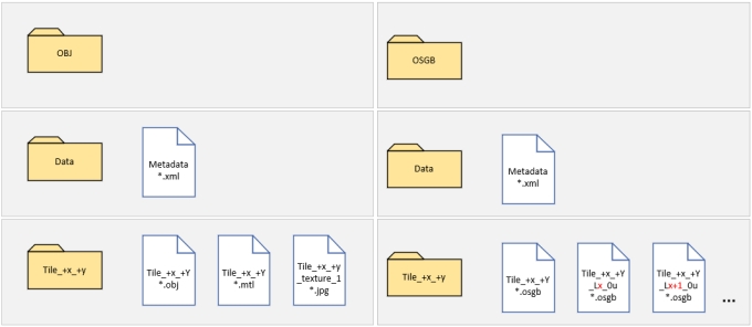
OBJ: OBJ is a 3D model file format for model editing and browsing. The .obj file mainly contains information about the vertices, normals, texture coordinates, and faces (triangles or polygons formed by vertices) of the 3D model. The *.mtl file defines the properties of the materials used in the model, such as colour, gloss, texture mapping, etc. The *.jpg file is the texture coordinates of the material. *.jpg files are texture maps.
OSGB: OSGB is a binary format for 3D model data, suitable for applications such as model browsing and real-time rendering.One of the features of the OSGB format is that it can support model representation with multiple Levels of Detail (LOD, Levels of Detail), which allows the system to dynamically load and display model levels of corresponding fineness according to the distance of the observer.
Use Multiple Origins:
When submitting a product, import a multi-origin planning file. It will automatically export the different tiles by origin.
Select Tiles:
Select the tiles of interest to be generated into a 3D model or point cloud.
② 3D point cloud product
After generating a 3D model, the model is sampled to produce a 3D point cloud product.
The software interface allows you to set the point cloud product output format, point cloud source, and resolution.
③ 2D product
After generating the 3D model, the model is sampled to generate DOM and DSM products.
The software interface allows you to set the sampling distance, image dimension, DOM product format, and DSM product format.
Select Grids:
Select the grids, which correspond to the grid divisions set up for the 3D reconstruction spatial frame.
Selection method is same with selecting tiles. The view shows areas that have not been reconstructed, have been reconstructed, and have been selected.
The software interface allows you to set the resolution, compression type, DOM product format, and DSM product format.
Get3D Mapper generates detailed AT Report and Reconstruction Report, allowing users to learn more about the details of aerial triangulation and reconstruction.
For projects that have completed Aerial Triangulation, an Aerial Triangulation report can be generated by clicking on View AT Report in the block view.
For projects with large image data, the process of generating this report takes some time.
The AT report contains an overview of the project, camera corrections, camera information, and tie point information. For projects that include control points information, the aerial triangulation report also contains control point information.
The project overview provides information on aerial triangulation time, mean ground resolution of photos, ground coverage, and the proportions of the photos in the net.
The correction of camera information contains the camera distortion parameters before and after calibration.
The camera information can be viewed as a legend with information such as the offset distance of the camera from the original POS data, the reprojection error for each photo, and the number of connection points observed by the camera, the scene coverage, and so on.
The tie point information can be visualized as a graphical representation of the number of observations and the reprojection error of the tie point.
For the project that includes control points, the aerial triangulation report also contains control point information. In the control point information, you can visualize the error distribution of control points and check points.
In the product interface, you can click View Product Report.
The reconstruction report contains Project Overview Information and Tile Information.
The project overview contains information about the coordinate system and origin of the modeled tiles, the size of the modeling area, and the time spent on the modeling.
The tool contains two functions: Merge DOM/DSM, and Model Origin Setting
Merge the generated DOM/DSM split images into a whole image. The specific use operation is as follows.
① Select the corresponding "Block", "Reconstruction" and "Product".
② Select the DOM and DSM of the products to be merged and set the output path.
③ Input the sample interval.
④ Set the correct coordinate system.
⑤ Click Merge button to start merging DOM/DSM.
For 3D models in OSGB format, due to limitations on decimal precision, data with ground resolutions at the centimeter level may experience a loss of precision when the model's position in the X or Y direction exceeds 10,000 meters from the origin during reconstruction. This can lead to visual issues such as flickering surfaces in the displayed model.
To address this, a model origin should be defined for every 10,000-meter grid to reduce the magnitude of model coordinate values.
3.3.9.1 Merge DOM/DSM
Merges the generated DOM/DSM split images into a whole image. The specific use operation is as follows.
① Import boundary KML/SHP.
② Set the initial origin coordinates, gird length and model origin position.
③ Model origin view.
④ Export model origin.
⑤ Import multi-origin file in product setting interface. Tiles will be exported automatically based on the defined origins.